- Details
- Last Updated: Friday, 30 December 2022 15:08
Lightweight Materials for encapsulating PV Modules on UAVs.
Goal: Develop lightweight materials for the new “Glassless Encapsulation©” process for encapsulating thin silicon solar cells on UAV Wings.
When powering a UAV with a photovoltaic module, the quantity of materials added on the UAV wings and fuselage is very critical due to weight limitation. Ultra-thin high efficiency silicon solar cells, if used, must be encapsulated on the top surfaces using special materials and without the traditionally used top glass sheets. It is desired that the encapsulant has a low density, high strength, and several other properties. It must allow to be applied in very thin films that provide sufficient protection to the cell front surface and a strong adhesion of the inflexible silicon cells on the fragile UAV surface. In addition, the encapsulation must yield conformal coverage to preserve the aerodynamics of the UAV.
To serve these purposes, we developed polymer materials that have high adhesion and high strength. Thanks to a new encapsulation process, the materials are applied in the form of very thin films, thinner than in conventional PV cell encapsulation that uses lamination technology. The top film yielded very smooth surface; deviations of the PV module thickness were less than 1% of the wing curvature radii. Though the applied films were very thin, they had enough strength and provided good adhesion to the cells. When applied under and above bent silicon cells, the cells remained mechanically stable at the end of the curing step. We have not observed delamination of the cells.
During the encapsulation process, the solar cells could endure the applied pressure, without initiating defects. The pressure was applied to ensure the conformal coverage. We limited the bending curvature to a threshold below which no micro-fractures and dislocations are generated. We have concluded that excessive bending causes the generation of internal defects that strongly degrade the PV cell efficiency. Various tests have been carried out to evaluate the degradation of cell performances and subsequently to ensure minimal current loss. While the cells are maintained under bending, the current-voltage (I-V) in the dark and under AM1.5 illumination conditions were analyzed. The solar cells were also stressed by cooling and heating them between 5°C to 55°C, under negative bias and while bent.
The cell I-V characteristic in reverse bias and the photogenerated current appeared to be very sensitive to the strain applied to the cell. They were used to depict the effect of the bending on the solar cell efficiency. While the solar cell is maintained under a fixed strain, the photocurrent showed oscillations as the negative voltage is decreased from 0 to -3V. Under high strains, spikes of current reduction appeared as the material relaxes. We believe that these current instability events occur when dislocation clusters are punched out, or micro-cracks are generated in weak points. However, these individual events did not invalidate the entire cell at once.
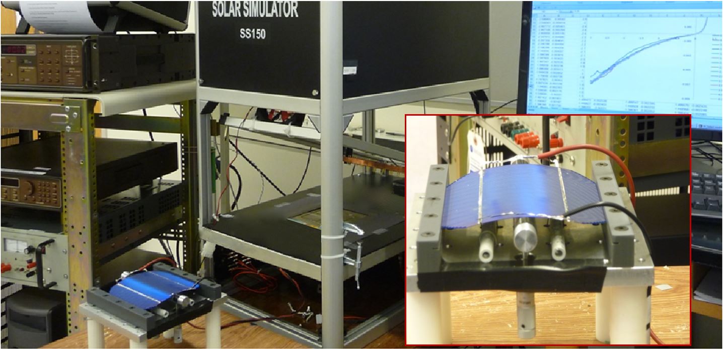
Fig. 1: Bent silicon cells prepared for current-voltage testing.
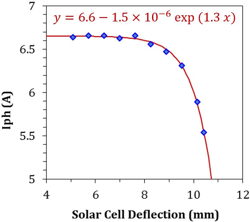
Six-inch and 180um thick monocrystalline silicon square cells were bent to match the wing curvatures. Though the cells are very thin, they are still rigid and brittle. The maximum bending before breaking was obtained for a deflection of 15mm, which corresponds to a curvature radius of 190mm. However, the solar cell efficiency starts to degrade above 8mm deflection, corresponding to a curvature radius of 350mm. As can be seen in Fig. 2, as the deflection is increased the collected photocurrent decreases, then accelerates exponentially.
| As far as the encapsulant material is concerned, it was required that any thermo-mechanical stress arising during the PV module operation should be absorbed by the encapsulant. For instance, stresses could be induced by increase of cell temperature by hotspots, these would add-up to the residual stress inherent to the encapsulation of cells on curved surfaces. Therefore, the encapsulant film had to be mechanically compliant to dissipate such stresses, which would otherwise severally degrade the efficiency of the effected cell, break it, or delaminate it. The cell being made of silicon is brittle. Damaged single cell, partially and more so totally, would result in a quicker aging of the entire module. |
Fig. 2: Degradation of the photocurrent of a 6” square monocrystalline silicon cells, due to applied mechanical stresses. |
To solve these issues, the thin polymer layer was designed with graded composition that had an elastic bulk material and a hard outer surface. The graded properties of the polymer film was obtained by stratifying ultrathin layers of poly-dimethyl-siloxane (PDMS) and Poly-Methyl-Meth-Acrylate (PMMA). To facilitate the development of the graded polymer layer, the strain and stress generated between the layers has been modeled by Finite element Analysis (FEA). For instance, we uncovered the factors of observed recession of the sublayers that occurs at the edges of the fabricated layer. We minimized their effect by optimizing the curing cycles.
Another requirement for the encapsulant is the transparency over the solar spectrum. This was achieved to an extent of 89-96% transmission for bubble free films. Furthermore, the antireflective property of the graded polymer film was assessed. By matching the refractive indexes of the sublayers and adjusting the film thicknesses, we could make the front layer to work as antireflective coating.
|
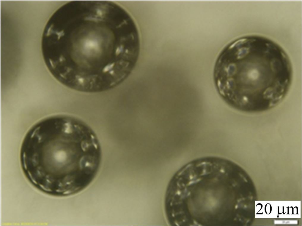
Other pertinent issue studied, for improving the bulk properties of this advanced encapsulant material, is the nucleation and growth of bubbles in the polymer components. The study included nanobuble generation, transport, and clustering mechanisms during the encapsulation process. The latter leads to buble growth to micro- and macro-scale sizes. Fig. 3shows the clustering of micro-bubbles in a PDMS layer that form giant bubbles. |
Fig. 3: Clustering of micro-buble in PDMS. |
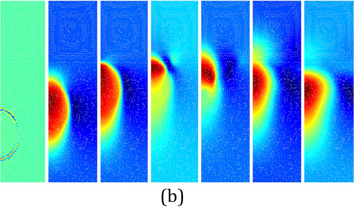
To understand the formation of nanobubles, and their subsequent growth, models have been developed and solved by FEA. These helped understanding four main issues: i) Diffusion of nitrogen, oxygen, water, and vaccum nanobubles in the polymer solution (these species are either produced as the polymers are mixed or captured from the ambient), ii) Nanobubble clustering and void formation in the polymer solution, and iii) Bubble flow in the polymer (based on kinetic theory of visco-elastic systems). We have not yet proved experimentally the formation of vacuum nanobubles in the polymer. Figure 4 shows some of the simulation data on bubble flow in the developed polymer. Also we tackled the miscibility of the polymer components forming a two-phase solution.
 |
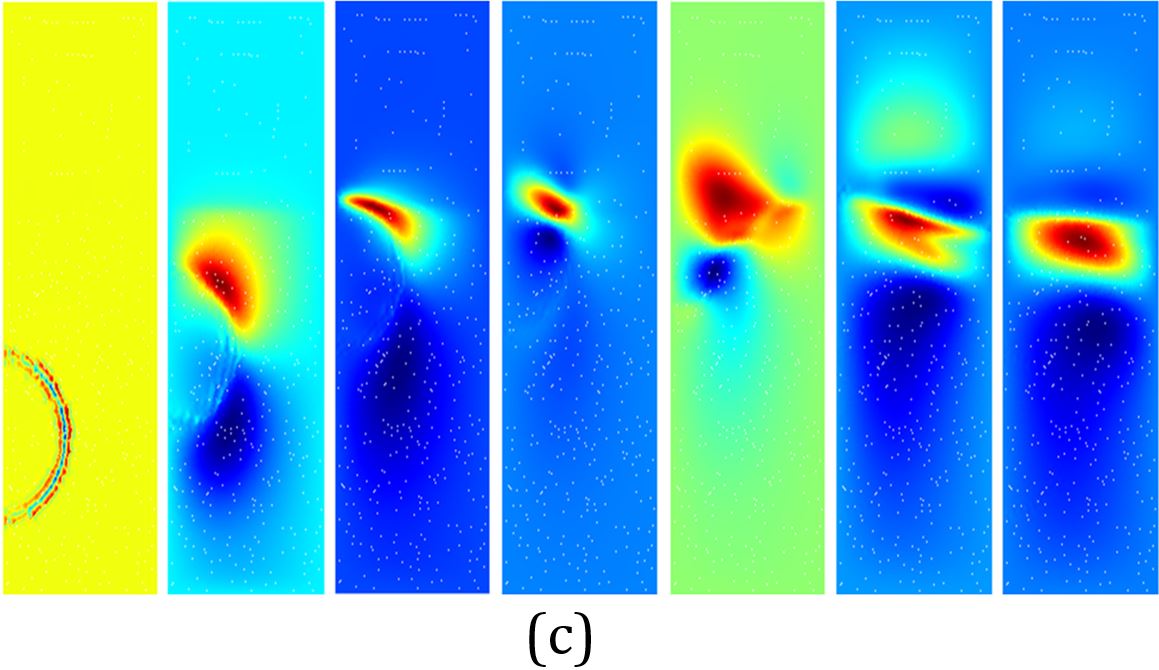 |
Fig. 4: a) Velocity field for micro-bubble flow in the polymer mixture, b) Buble axial velocity during the flow, c) Radial velocity.
.
