- Details
- Last Updated: Monday, 26 December 2022 05:19
Increasing Float Zone Silicon Toughness for high Efficiency Silicon Solar Cells, through Locking Dislocation with Impurities
Float Zone (FZ) silicon is important for high efficiency solar cells, such as Sliver Solar Cells, and many microelectronics applications, where high minority lifetime substrates are desired. Lifetimes in the order of 10 to 12 ms have been reported, however, FZ Si wafers are brittle and inherently fragile. We proposed to dope FZ silicon with nitrogen (NFZ) to strengthen the material substrate. This project was funded by the National Renewable Energy Lab (NREL).
Similar projects contracted with three photovoltaic companies, i.e, BP Solar, Astropower/GE, and Evergreen, with support from NREL, for studying the effect of nitrogen on the impurity gettering in polycrystalline silicon and on grain boundary structure and impurity gettering properties has been performed by our group. The ultimate goal was to strengthen ultra-thin polycrystalline silicon wafers that originally incur excessive breakage during wafer handling and solar cell fabrication. The breakage presented a very serious issue for photovoltaic manufacturers, when using thin polycrystalline silicon. Because the material is low cost and promising for photovoltaic (PV) industry, the problem was tackled both experimentally and theoretically. One aspect of this work, presented here, is the modeling of dislocation locking by O, N, and other important impurities.
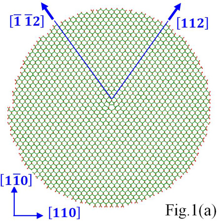
The increase of float zone (FZ) silicon toughness can be achieved through an increase of the effectiveness of dislocation locking by impurities and point defects. Practically, FZ silicon doping and co-doping with N and O enables efficient control of dislocation motion. To understand these effects, molecular dynamics (MD) calculations were done and the interaction of dislocations with single impurity atom and clusters were analyzed. The atomic atmosphere distribution around the dislocation core, its density, the binding energy of impurities to dislocation, and the generated forces by the impurity atmosphere (i.e., pressure on the dislocation line) were calculated at various annealing temperatures for an edge dislocation in FZ silicon.
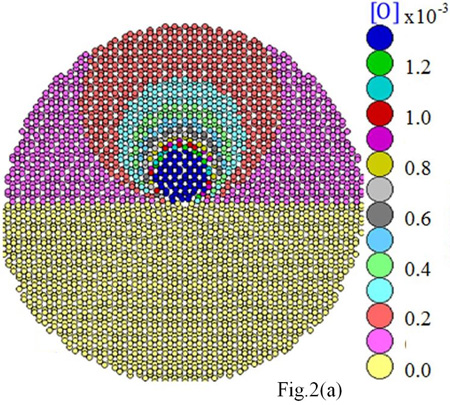
We found that O, N, and C atoms spread over a cylinder whose radius is about 7 neighboring lattice sites from the dislocation line. These light elements yield atmospheres about the dislocation with similar densities. Remarkably, O and N atoms are found concentrated close to the dislocation core. In contrast, Ge is only moderately gettered by the dislocation. A comparative example for these contrasted behaviors is given in Fig. 2, where in (a) we show the calculated distribution of O atoms around the dislocation at 1100°C, and in (b) the distribution of larger atoms, here Ge. The strain field induced around the dislocation changes from tensile, for O, to compressive, for Ge.
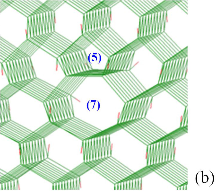
For O contaminated dislocation, the penta-ring and the upper hexa-ring, both in the compressive part of the dislocation domain, are the most likely zones for the localization of oxygen atoms; whereas the septa-ring which is in the dilation side of the dislocation (lower part) repels O atoms. Likewise, N and C in tetrahedral interstitial positions locate themselves in the compressive side of the dislocation. It is important to note that carbon is distributed around the dislocation in a slightly more diffuse way than nitrogen.
 |
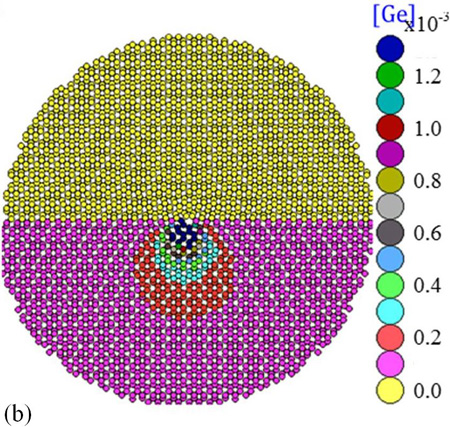 |
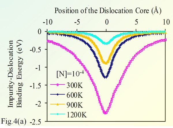
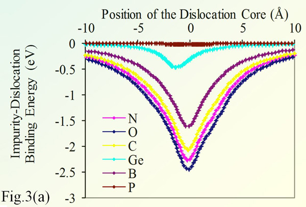
Fig. 3(a) shows the binding energy of 90° dislocation in silicon with various impurities. The impurity concentration is 10-4 (relative to silicon), and the temperature is 300°K. The chart shows that O strongly binds to dislocations, hence can efficiently lock it. Nitrogen is the impurity with closest behavior to O, which justifies its use as alternative to O for strengthening silicon. In contrast, P does not bind with the edge dislocation.
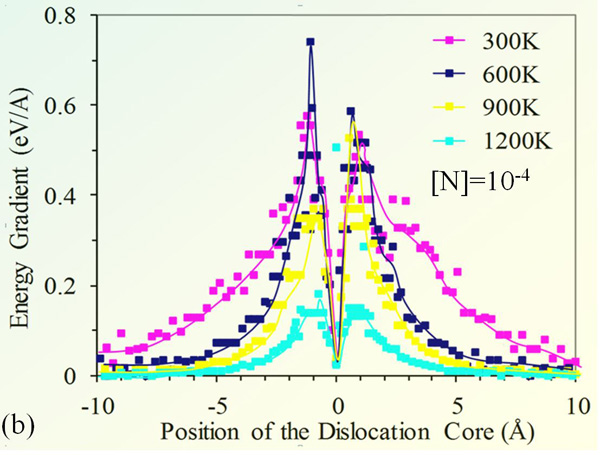
Fig. 3(b) provides the shear force acting on the edge dislocation; the force is deduced from the binding energy gradient. The maximum shear force occurs at the inflection point of the energy diagram. It is remarkable that the force practically vanishes when the impurity atmosphere is few nanometers away from the dislocation core. It reaches its peak value when the impurity is right at the edge of the dislocation core. The force ultimately ceases as the impurity surrounds the dislocation core.
 |
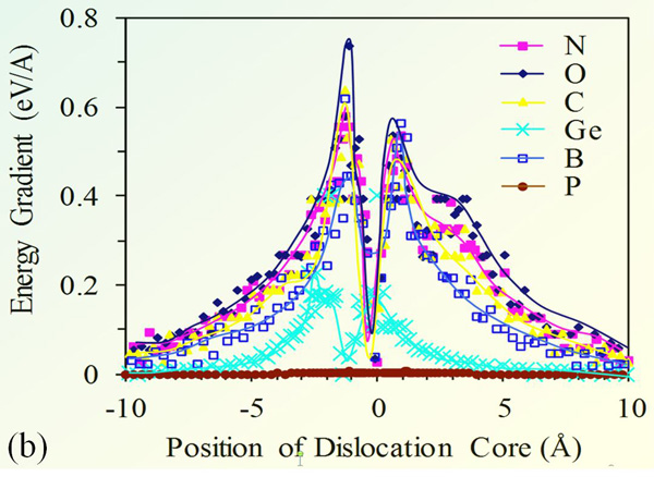 |
The shear stress data suggests that dislocation is free to move within 4 Å off its equilibrium position, the range is within the potential well associated to the shear stress well. The dislocation can freely move within a cylindrical shell, without any resistance from the impurity atmosphere.
